This module is related method which convert to horizontal parallax only hologram.
Introduction
- The hologram contains all the information of a 3D object and require a large amount of transmission for use in a holographic display. However, because the capacity of the information transmission channel is limited, a great amount of research has been spent on holographic information reduction so as to facilitate, for example, TV transmission of holograms. A horizontal-parallax-only (HPO) hologram has been proposed as an excellent way to reduce the required amount of data for 3D display [1,2].
- Recently, HPO optical scanning holography(OSH) has been suggested as an electro-optical technique that actually records the holographic information of a real object without vertical parallax [3]. However, the proposed HPO OSH will introduce aberration upon optical reconstruction along the vertical direction if the vertical extent of the asymmetrical Fresnel zone plate (FZP), which has been proposed to generate the HPO data from a real object, is not small enough [3,4]. To eliminate aberration caused by the asymmetrical FZP, an algorithm that converts a recorded full-parallax (FP) hologram to an HPO hologram was subsequently proposed [4]. The converted HPO hologram was optically reconstruct using a conventional amplitude-only spatial light modulator (SLM) [5].
Algorithm
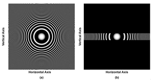
- This method that converts a full-parallax hologram to an HPO hologram by using Gaussian low-pass filtering and fringe-matched filtering. Although a full-parallax hologram of a 3D object can be considered as a collec tion of 2D Fresnel zone plates (FZPs), an HPO hologram is a collection of 1D FZPs [3]. Figures 1(a) and 1(b) show a 2D FZP and an asymmetrical FZP, respectively. The asymmetrical FZP shown in Fig. 1(b) illustrates an approx imation to a line or 1D FZP by masking a slit along the x direction. Note that the asymmetrical FZP still has curvature within its vertical extent if the slit size is not small enough, and hence it will generate aberrat ion upon reconstruction of the hologram.

Figure 1. (a) Full-parallax FZP, (b) asymmetrical FZP.
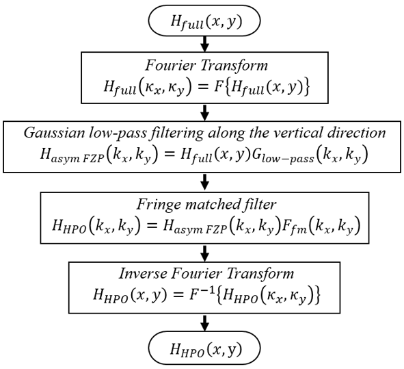
- Gaussian low-pass filtering along the vertical direction removes the high-frequency components of the object along the vertical direction. This makes it possible to reduce the amount of data by sacrificing the vertical parallax without losing the horizontal parallax. The filtered output becomes a hologram in which the object is encoded by an asymmetrical FZP.
- Fringe-matched filter compensates the curvature of the Gaussian low-pass filtered hologram along the vertical direction and gives an exact HPO hologram as an output [1,2]. This makes it possible to removes the curvature along the vertical direction of the asymmetrical FZP.
- First, the full parallax complex hologram of the object obtained using the OSH setup is given by the following [6]:
\[ H_{full}(x,y)=\int_{z_0-\Delta z}^{z_0+\Delta z}I_0(x,y,z) \otimes \frac{j}{\lambda z} \times \exp \left \{ \left(\frac{\pi}{NA^2z^2}+j \frac{\pi}{\lambda z}\right)\left(x^2+y^2\right) \right \}dz \qquad \left(1\right) \]
- Where \(NA\) represents the numerical aperture defined as the sine of the half-cone angle subtended by the TD-FZP, \(\lambda\) is the wavelength of the laser, \(z_0\) is the depth location of the object, \(2\Delta z\) is the depth range of the object, and the symbol \(\otimes\) denotes 2D convolution. The spectrum of the hologram is given by
\[ H_{full}(k_x,k_y)=F\left\{H_{full}(x,y)\right\} =\int_{z_0-\Delta z}^{z_0+\Delta z}I_0(k_x,k_y,z) \times \exp \left \{ \left[-\frac{1}{4\pi}\left(\frac{\lambda}{NA}\right)+j \frac{\lambda z}{\lambda \pi}\right] \left(k_x^2+k_y^2\right) \right \}dz \qquad \left(2\right) \]
- Where \( F\left\{.\right\}\). represents Fourier transformation with \(\left(k_x,k_y\right)\) denoting spatial frequencies.
- Next apply a Gaussian low-pass filter along the vertical direction, \( G_{low-pass}\left(k_x,k_y\right)=\exp\left[\frac{-1}{4\pi} \left(\frac{\lambda}{NA_g} \right)^2k_y^2 \right]\), to the full-parallax hologram’s spectrum given by Eq. (2), where \( NA_g \) is a parameter that determines the cut off frequency of the Gaussian low-pass filter. The filtered spectrum is then given by
\[ H_{asym\ FZP}\left(k_x,k_y\right) =H_{full}\left(x,y\right)G_{low-pass}\left(k_x,k_y\right) =\int_{z_0-\Delta z}^{z_0+\Delta z}{I_0(k_x,k_y,z) \times \exp\left\{\left[-\frac{1}{4\pi}\left(\frac{\lambda}{NA}\right)^2+j\frac{\lambda z}{4\pi}\right]k_x^2+ \left[-\frac{1}{4\pi}\left(\frac{\lambda}{{NA}_{lp}}\right)^2+j\frac{\lambda z}{4\pi}\right]k_y^2\right\}}dz \qquad \left(3\right) \]
- Where \({\rm NA}_{lp}={\rm NA}_gNA/\sqrt{{\rm NA}^2+{NA}_g^2}\) is the NA of the FZP along the vertical direction. Note that the Gaussian low-pass filtered hologram is a hologram in which the object’s cross-sectional images are encoded with the asymmetrical FZP. As discussed earlier, the asymmetric FZP has curvature along the vertical direction. To remove the curvature, use a fringe-matched filter, \(F_{fm}\left(k_x,k_y\right)=exp\left[-j\lambda z_0/4\pi k_y^2\right]\), that compensates the curvature along the vertical direction, where \(z_0\) is the depth location of the object. Hence the fringe-adjusted filtered output becomes
\[ H_{HPO}\left(k_x,k_y\right) =H_{asym\ FZP}\left(k_x,k_y\right)F_{fm}\left(k_x,k_y\right) =\int_{z_0-\Delta z}^{z_0+\Delta z}{I_0(k_x,k_y,z)\times \exp\left\{\left[-\frac{1}{4\pi} \left(\frac{\lambda}{NA}\right)^2+j\frac{\lambda z}{4\pi}\right]k_x^2+{\left[-\frac{1}{4\pi} \left(\frac{\lambda}{{NA}_{lp}}\right)^2+j\frac{\lambda\left(z-z_0\right)}{4\pi}\right]k}_y^2\right\}}dz \qquad \left(4\right) \]
- The HPO hologram in space domain is given by \( H_{HPO}\left(x,y\right)=F^{-1}\left\{H_{HPO}\left(k_x,k_y\right)\right\}\), where \( F^{-1}\left\{.\right\} \). Represents the inverse Fourier transformation. Now, in the case that the depth range of the object \( \left(2\Delta z\right)\) is smaller than the in-focus range of the line FZP along the vertical direction \( \left(2\Delta z_{ver_dir}=2\lambda/\left({NA}_{lp}^2\right)\right)\), i.e., \( \Delta z\le\Delta z_{ver_dir}\), which is usually true when we synthesize an HPO hologram for 3D display, \( z\approx z_0\) within the range of the object depth along the y direction, and hence the last term of the exponential function become zero, i.e., \( \lambda\left(z-z_0\right)/4\pi\approx 0\). Equation (4) then becomes
\[ H_{HPO}\left(k_x,k_y\right) =\int_{z_0-\Delta z}^{z_0+\Delta z}{I_0(k_x,k_y,z) \times \exp\left\{\left[-\frac{1}{4\pi}\left(\frac{\lambda}{NA}\right)^2+j\frac{\lambda z}{4\pi}\right]k_x^2 +{\left[-\frac{1}{4\pi}\left(\frac{\lambda}{NA_{lp}}\right)^2\right]k}_y^2\right\}}dz \qquad \left(5 \right ) \]
- and its spatial domain expression is
\[ H_{HPO}\left(x,y\right)=F^{-1}\left\{H_{HPO}\left(k_x,k_y\right)\right\} =\int_{z_0-\Delta z}^{z_0+\Delta z}{I_0(x,y,z)\otimes\frac{j}{\lambda z} \times \exp\left\{-\left[-\left(\frac{\pi}{NA^2z^2}\right)+j\frac{\pi}{\lambda z}\right]x^2 +\frac{\lambda}{NA_{lp}^2z^2}y^2\right\}}dz \qquad (6) \]

Figure 2. Flowchart
Reference
- [1] P. St. Hilaire, S. A. Benton, and M. Lucente, “Synthetic aperture holography: a novel approach to three-dimensional displays,” J. Opt. Soc. Am. A 9, 11, 1969-1977 (1992).
- [2] H. Yoshikawa and H. Taniguchi, “Computer Generated Rainbow Hologram,” Opt. Rev. 6, 118 (1999).
- [3] T.-C. Poon, T. Akin, G. Indebetouw, and T. Kim, “Horizontal parallax-only electronic holography,” Opt. Express 13, 2427–2432 (2005).
- [4] T. Kim, Y. S. Kim, W. S. Kim, and T.-C. Poon, “Algorithm for converting full-parallax holograms to horizontal parallax-only holograms,” Opt. Lett. 34, 1231–1233 (2009).
- [5] Y. S. Kim, T. Kim, T.-C. Poon, and J. T. Kim, “Three-dimensional display of a horizontal-parallax-only hologram,” Applied Optics Vol. 50, Issue 7, pp. B81-B87 (2011)
- [6] T.-C. Poon, T. Kim, G. Indebetouw, M. H. Wu, K. Shinoda, and Y. Suzuki, “Twin-image elimination experiments for three-dimensional images in optical scanning holography,” Opt. Lett. 25, 215 (2000).
◆ sigConvertHPO()
| bool ophSig::sigConvertHPO |
( |
Real |
depth, |
|
|
Real_t |
redRate |
|
) |
| |
Function for convert complex hologram to horizontal parallax only hologram.
- Parameters
-
| depth | Position from hologram plane to propagation hologram plane |
| redRate | data reduction rate |
- Returns
- If works well return 0 or error occurs return -1
Definition at line 1014 of file ophSig.cpp.
◆ sigConvertHPO_CPU()
| bool ophSig::sigConvertHPO_CPU |
( |
Real |
depth, |
|
|
Real_t |
redRate |
|
) |
| |
|
protected |
Function for convert complex hologram to horizontal parallax only hologram by using CPU.
- Parameters
-
| depth | Position from hologram plane to propagation hologram plane |
| redRate | data reduction rate |
- Returns
- If works well return 0 or error occurs return -1
Definition at line 1145 of file ophSig.cpp.
◆ sigConvertHPO_GPU()
| bool ophSig::sigConvertHPO_GPU |
( |
Real |
depth, |
|
|
Real_t |
redRate |
|
) |
| |
|
protected |
Function for convert complex hologram to horizontal parallax only hologram by using GPU.
- Parameters
-
| depth | Position from hologram plane to propagation hologram plane |
| redRate | data reduction rate |
- Returns
- If works well return 0 or error occurs return -1
Definition at line 119 of file ophSig_GPU.cpp.


