This module is related method which compensate of full color hologram with chromatic aberration.
Introduction
- Recording holographic information of a real object as a form of electric signal has a long history [1,2]. Optical scanning holography (OSH) proposed to record a hologram of a real object using heterodyne scanning [3,4]. Twin-image noise in OSH was eliminated by recording a complex hologram using in-phase and quadrature(Q)-phase heterodyne detection scheme [5]. speckle-free recording of a complex hologram using OSH has been demonstrated [6]. Recently full-color OSH has been proposed and shows that the full-color complex hologram of a real object can be recorded by two dimensional (2D) scanning [7].
- Meanwhile, digital holography has been intensively investigated for recording a hologram of a real object for a three-dimensional (3D) imaging system as well as industrial metrology applications [8,9]. Recently, color digital holography has been proposed and chromatic aberration compensation techniques are investigated [11-15]. As in color digital holography, the chromatic aberration issue has also been emerged in full-color OSH. In this paper, I will investigate the chromatic aberration issue of full-color OSH and propose a digital filtering technique that compensates the chromatic aberration.
Algorithm
- The complex RGB holograms that are encoded pattern between RGB FZPs and object’s RGB reflectances are given by [7]:
\[ H_n (x,y)=\int I_n (x,y,z)\otimes \frac{j}{\lambda_n z_n}\exp{\left(-\frac{\pi}{NA_n^2 z_n^2}+j\frac{\pi}{\lambda_n z_n} \right)(x^2+y^2 )}dz, \quad n={R,G,B} \qquad (1) \]
- Where \( \otimes \) represents 2D convolution operation, \( I_n(x,y,z) \) are the RGB reflectances of the object, \( λ_n \) are the wave length of RGB beams, \( z_n \) are the distance between the focal points of RGB spherical waves to the object’s RGB reflectances distributions and \( NA_n \) represent the numerical apertures defined as the sine of the half-cone angle subtended by RGB spherical waves.
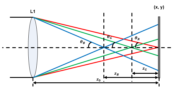
- Full-color OSH has chromatic aberration issue. fig. 1. represents the RGB spherical waves generated by L1 where L1 is made of conventional material whose refractive index decreases as wavelength increases in visible range. Since the refractive index of the material depends on the wavelength, the location of the focal points of the RGB spherical waves are different as shown in fig. 1.

Figure 1. RGB spherical waves generated by the lens L1.
- The focal length of a conventional bi-convex lens is given by :
\[ f=\frac{1}{(n_l-1)\left[\frac{2}{R}-\frac{(n_l-1)d}{n_l R^2}\right]} \qquad (2) \]
- Where \( n_l\) is the refractive index of the lens L1, \( R\) is the front and back radii of curvature and \(d\) is the center thickness of the lens L1. As shown in Eq (1), the RGB holograms are encoded patterns between the spatial distribution of the object’s RGB reflectances and RGB FZPs. We note that the focal lengths of the RGB spheri cal waves are different according the Eq (2). This makes the distances \((Z_n)\) from the focal points of the RGB spheri cal waves to the object’s RGB reflectances distributions, and the numerical apertures \((NA_n=\sin\theta_n)\) of the RGB FZPs depend on the wavelengths of RGB beams. Since the \(Z_n\) and the \(NA_n\) of the RGB FZPs are different according to the RGB beams, the recorded RGB holograms are reconstructed at different depth locations with different divergence angles. This causes chromatic aberration as in the conventional imaging system.
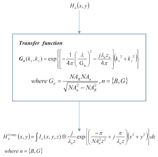
- We need to match the NAs and focal lengths of RGB FZPs each other. Because focal length and NAs of the RGB FZPs in recorded RGB holograms are different according to the wavelengths. Chromatic aberration compensation filter (CAC) matches the NAs and focal lengths of the RGB FZPs of the recorded RGB hologram. The fig. 2 shows the CAC filter that matches the NAs and focal lengths of the GB FZPs in the GB holograms to those of the R FZP in the R hologram, where \((k_x,k_y)\) is the spatial frequencies, \(G_n\) are the extent of the CAC filter and \(z_n\) are the focal length differences as shown in fig. 1.
- The extent of CAC filter \(G_n\) match the NAs of the GB FZPs to the NA of the R hologram. The fringes of the CAC filter determined by \(\lambda_n z_n\) match the focal lengths of GB FZPs to the focal length of the R FZP.

Figure 2. Flowchart.
Reference
- [1] C. Burckhardt and L. Enloe, "Television transmission of holograms with reduced resolution requirements on the camera tube," Bell Syst. Tech.Jour 45, 1529–1535 (1969).
- [2] J. Berrang, "Television transmission of holograms using a narrow-bandvideo signal," Bell Syst. Tech. J 879–887 (1970).
- [3] T. C. Poon and a Korpel, "Optical transfer function of an acousto-opticheterodyning image processor," Opt. Lett. 4, 317–9 (1979).
- [4] T.-C. Poon, "Scanning holography and two-dimensional image processing by acousto-optic two-pupil synthesis," J. Opt. Soc. Am. A 2, 521 (1985).
- [5] T. C. Poon, T. Kim, G. Indebetouw, B. W. Schilling, M. H. Wu, K.Shinoda, and Y. Suzuki, "Twin-image elimination experiments for threedimensional images in optical scanning holography," Opt. Lett. 25, 215–7 (2000).
- [6] Y. S. Kim, T. Kim, S. S. Woo, H. Kang, T. C. Poon, and C. Zhou,"Speckle-free digital holographic recording of a diffusely reflecting object," Opt. Express 21, 8183–8189 (2013).
- [7] H. Kim, Y. S. Kim, T. Kim, “Full-color optical scanning holography with common Red, Green and Blue channels,” Appl. Opt. 50, B81–B87 (2016).
- [8] U. Schnars, “Direct phase determination in hologram interferometry with use of digitally recorded holograms,” J. Opt. Soc. Am. A 11, 2011–2015 (1994).
- [9] I. Yamaguchi and T. Zhang, “Phase-shifting digital holography,” Opt.Lett. 22, 1268–1270 (1997).
- [10] U. Schanrs and W. Jueptner, Digital Holography, Springer (2005).
- [11] I. Yamaguchi, T. Matsumura, and J. Kato, “Phase-shifting color digital holography,” Opt. Lett. 27, 1108–1110 (2002).
- [12] P. Memmolo, A. Finizio, M. Paturzo, P. Ferraro, and B. Javidi “Multiwavelengths digital holography: reconstruction, synthesis and display of holograms using adaptive transformation” Opt. Lett. 37, No. 9, 1445-1447 (2012)
- [13] M. K. Kim “Full color natural light holographic camera” Opt. Express 21, No. 8, 9636-9642 (2013)
- [14] T. Tahara, Y. Ito, Y. Lee, P. Xia, J. Inoue, Y. Awatsuji, K. Nishio, S. Ura, T. Kubota, and O. Matoba “Multiwavelength parallel phase-shifting digital holography using angular multiplexing” Opt. Lett. 38, No. 15, 2789-2791 (2013)
- [15] J. Dohet-Eraly, C. Yourassowsky, and F. Dubois “Refocusing based on amplitude analysis in color digital holographic microscopy” Opt. Lett. 39, No. 5, 1109-1112 (2014)
◆ sigConvertCAC()
| bool ophSig::sigConvertCAC |
( |
double |
red, |
|
|
double |
green, |
|
|
double |
blue |
|
) |
| |
Function for Chromatic aberration compensation filter.
- Parameters
-
| red | Red wavelength |
| Green | Green wavelength |
| Blue | Blue wavelength |
- Returns
- If works well return 0 or error occurs return -1
Definition at line 1035 of file ophSig.cpp.
◆ sigConvertCAC_CPU()
| bool ophSig::sigConvertCAC_CPU |
( |
double |
red, |
|
|
double |
green, |
|
|
double |
blue |
|
) |
| |
|
protected |
Function for Chromatic aberration compensation filter by using CPU .
- Parameters
-
| red | Red wavelength |
| green | Green wavelength |
| blue | Blue wavelength |
- Returns
- If works well return 0 or error occurs return -1
Definition at line 1191 of file ophSig.cpp.
◆ sigConvertCAC_GPU()
| bool ophSig::sigConvertCAC_GPU |
( |
double |
red, |
|
|
double |
green, |
|
|
double |
blue |
|
) |
| |
|
protected |
Function for Chromatic aberration compensation filter by using GPU.
- Parameters
-
| red | Red wavelength |
| green | Green wavelength |
| blue | Blue wavelength |
- Returns
- If works well return 0 or error occurs return -1
Definition at line 181 of file ophSig_GPU.cpp.


