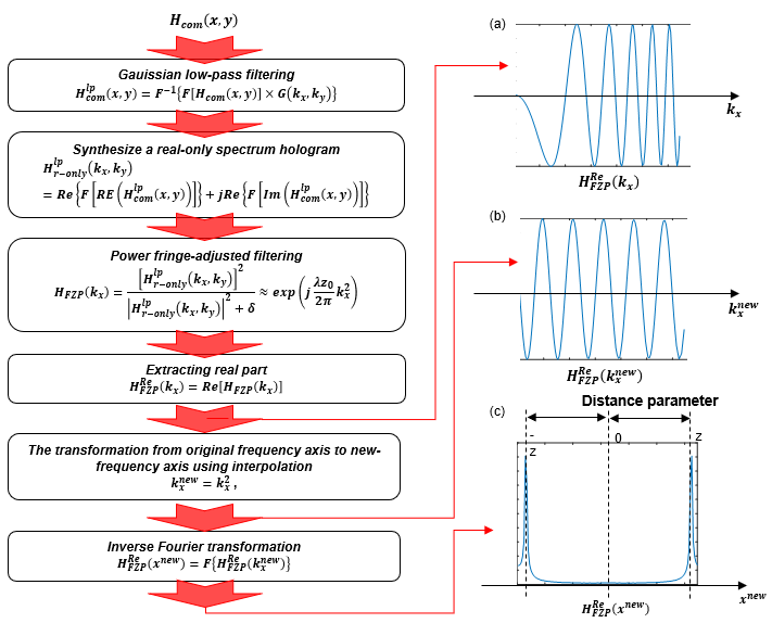
This module is related method which extraction of distance parameter using axis transformation method.
Introduction
- OSH is reconstructed digitally by convolving the complex conjugate of Fresnel zone plate (FZP) with the hologram. This is the same as conventional digital holography, in which the FZP’s distance parameter is set according to the depth location of the objects. However, since the depth location of the objects is unknown, digital reconstructions with different distance parameters are required until we get a focused image.
- Unfortunately, this searching process is time consuming and requires a manual process. Recently several numerical techniques that extract the distance parameter directly from the hologram without reconstructions have been proposed [1-3]; however, these involve a search algorithm [2,3] or a tracking process [1]. Most recently, an auto-focusing technique based on the Wigner distribution analysis of a hologram has been proposed [4].
- In the proposed technique, we extract the distance parameter directly from the hologram without any searching or tracking process. However, a manual process that measures the slope of the Wigner distribution output is required in order to determine the distance parameter. Therefore, we propose to extract the distance parameter directly from the hologram using axis transformation without any manual processes.
Algorithm
- First, the complex hologram is filtered by a Gaussian low-pass filter with transfer function. The Gaussian low-pass filtered hologram is given by the following equation:
\[ H_{com}^{lp}\left(x,y\right)=F^{-1}\left\{F\left[H_{com}\left(x,y\right)\right]\times G\left(k_x,k_y\right)\right\} =\int_{z_0-\frac{1}{2}\delta z}^{z_0+\frac{1}{2}\delta z}I_o\left(x,y,z \right)\otimes\frac{j}{\lambda z} \exp\left[\left(\frac{-\pi}{a_{lp} z^2}-j\frac{\pi}{\lambda z}\right)\left(x^2+y^2\right)\right]dz \qquad (1) G\left(k_x,k_y\right)=exp\left\{-\pi\left[\frac{\lambda}{2\pi{NA}_g}\right]^2\left({k_x}^2+{k_y}^2\right)\right\} \]
- Where \(F{.}\) represents the Fourier transform operator, \(a_{lp}\left(z\right)=NA_gNA/\sqrt{NA^2+NA_g^2}\times z\) determines the radius of the Gaussian low pass filtered hologram. Hence, the Reyleigh range of the Gaussian low-pass filtered hologram evolves into the following equation:
\[ \Delta z=2{\lambda z}^2/{{(a}_{lp}z}^2\ \pi)=2\lambda/\pi\times({NA}^2+{NA}_g^2)/{({NA}_gNA)}^2 \]
- In Gaussian low pass filtering, we set \(NA_g\) such that the Rayleigh range of the FZP is larger than the depth range of the object, i.e. \(\Delta z\geq\delta z\). The radius of the scanning beam pattern is approximately constant within the depth range of the object. This makes the phase of the Gaussian low pass filtered hologram stationary within the depth range of the specimen [4, 5]; thus, we can extract the FZP which contains the information only about the distance parameter from the hologram.
- Second, a real-only spectrum hologram in the frequency domain is synthesized and is given by the following:
\[ H_{r-only}^{lp}\left(k_x,k_y\right)=Re\left\{F\left[Re\left(H_{com}^{lp}\left(x,y\right)\right)\right]\right\} +jRe\left\{F\left[Im\left(H_{com}^{lp}\left(x,y\right)\right)\right]\right\} \qquad (2) \]
- After projecting the real-only spectrum hologram onto the ky direction, we filter the square of the projected real-only spectrum hologram by a power-fringe-adjusted filter [6-9]. The power-fringe-adjusted filtered output is given by:
\[ H_{FZP}\left(k_x\right)=\frac{\left[\int{H_{r-only}^{lp}\left(k_x,k_y\right)dk_y}\right]^2}{\left|\int{H_{r-only}^{lp} \left(k_x,k_y\right)dk_y}\right|^2+\delta}\approx exp\left(j\frac{\lambda z_0}{2\pi}k_x^2\right) \qquad (3) \]
- Eq. (3), the filtered output is a chirping signal whose chirping rate is determined by the distance parameter. Note that the filtered output is the one-dimensional FZP with the distance parameter.
- Third, the real part of Eq. (3) is extracted and is given by the following:\ .\
\[ H_{FZP}^{Re}\left(k_x\right)=Re\left\lfloor H_{FZP}\left(k_x\right)\right\rfloor \approx cos\left(\frac{\lambda z_0}{2\pi}k_x^2\right) \qquad (4) \]
- \(H_{FZP}^{Re}\left(k_x\right)\) shown as fig.1-a.
- Fourth, the transformation from original frequency axis to new-frequency axis using interpolation.
\[ k_x^{new}=k_x^2\ , H_{FZP}^{Re}\left(k_x^{new}\right)\approx cos\left(\frac{\lambda z_0}{2\pi}k_x^{new}\right) \qquad (5) \]
- Note that this sinusoidal signal has a single frequency and the frequency of the signal is directly proportional to the distance parameter. Hence, the inverse Fourier transformation of Eq.(5) expresses the delta function pair in the new spatial axis:
\[ h_{FZP}^{Re}\left(x^{new}\right) =\mathbf{F}^{-\mathbf{1}}\left\{H_{FZP}^{Re}\left(k_x^{new}\right)\right\} \approx\frac{1}{2}\delta\left(x^{new}-\frac{\lambda z_0}{2\pi}\right)+\frac{1}{2}\delta\left(x^{new}+\frac{\lambda z_0}{2\pi}\right) \qquad (6) \]
- Note that the location of the delta function pair gives the distance parameter. This can be extracted directly by detecting the location of the maximum value of Eq. (6).

Figure 1. Flowchart.
Reference
- [1] P. Ferraro, G. Coppola, S. D. Nicola, A. Finizio, and G. Pierattini, “Digital holographic microscope with automatic focus tracking by detecting sample displacement in real time,” Opt. Lett. 28, 1257-1259 (2003).
- [2] M. Liebling and M. Unser, “Autofocus for digital Fresnel holograms by use of a Fresnelet-sparsity criterion,” J. Opt. Soc. Am. A 21, 2424-2430 (2004).
- [3] P. Langehanenberg, B. Kemper, D. Dirksen, and G. von Bally, “Autofocusing in digital holographic phase contrast microscopy on pure phase objects for live cell imaging,” Appl. Opt. 47, D176 (2008).
- [4] T. Kim and T.-C. Poon, “Auto-focusing in optical scanning holography,” Appl. Opt. 48, H153-H159 (2009).
- [5] T. Kim, Y. S. Kim, W. S. Kim, and T.-C. Poon, “Algorithm for converting full-parallax holograms to horizontal parallax -only holograms,” Opt. Lett. 34, 1231-1233 (2009).
- [6] T. Kim and T.-C. Poon, “Extraction of 3-D location of matched 3-D object using power fringe-adjusted filtering and Wigner analysis,” Opt. Eng. 38, 2176-2183 (1999).
- [7] T. Kim and T.-C. Poon, “Experiments of depth detection and image recovery of a remote target using a complex hologram,” Opt. Eng. 43, 1851-1855 (2004).
- [8] T. Kim, T.-C. Poon, and G. Indebetouw, ‘‘Depth detection and image recovery in remote sensing by optical scanning holography,’’ Opt. Eng. 41, 1331-1338 (2002).
- [9] P. Klysubun, G. Indebetouw, T. Kim, and T.-C. Poon, ‘‘Accuracy of three-dimensional remote target location using scanning holographic correlation,’’ Opt. Comm. 184, 357 -366 (2000).
◆ sigGetParamAT()
| double ophSig::sigGetParamAT |
( |
| ) |
|
Extraction of distance parameter using axis transfomation.
- Returns
- Result distance
Definition at line 1387 of file ophSig.cpp.
◆ sigGetParamAT_CPU()
| double ophSig::sigGetParamAT_CPU |
( |
| ) |
|
|
protected |
Extraction of distance parameter using axis transfomation by using CPU.
- Returns
- Result distance
Definition at line 1412 of file ophSig.cpp.
◆ sigGetParamAT_GPU()
| double ophSig::sigGetParamAT_GPU |
( |
| ) |
|
|
protected |
Extraction of distance parameter using axis transfomation by using GPU.
- Returns
- Result distance
Definition at line 456 of file ophSig_GPU.cpp.


